General measurement method of ultrasonic thickness gauge
(1) Use the probe to measure the thickness twice at one point. In the two measurements, the split surfaces of the probe should be 90° to each other, and the smaller value is taken as the thickness value of the workpiece being measured.
(2) 30mm multi-point measurement method: When the measurement value is unstable, take one measurement point as the center and make multiple measurements within a circle with a diameter of about 30mm. Take the minimum value as the thickness value of the workpiece being measured.
- Ultrasonic thickness gauge precision measurement method
Increase the number of measurements around the specified measurement point, and the thickness change is represented by equal thickness lines. - Ultrasonic thickness gauge continuous measurement method
Use the single-point measurement method to measure continuously along the specified route, with an interval of no more than 5mm. - Ultrasonic thickness gauge grid measurement method
Draw a grid in the specified area and record the thickness measurement point by point. This method is widely used in high-voltage equipment and stainless steel lining corrosion monitoring.
4. Factors affecting the indication of ultrasonic thickness gauge
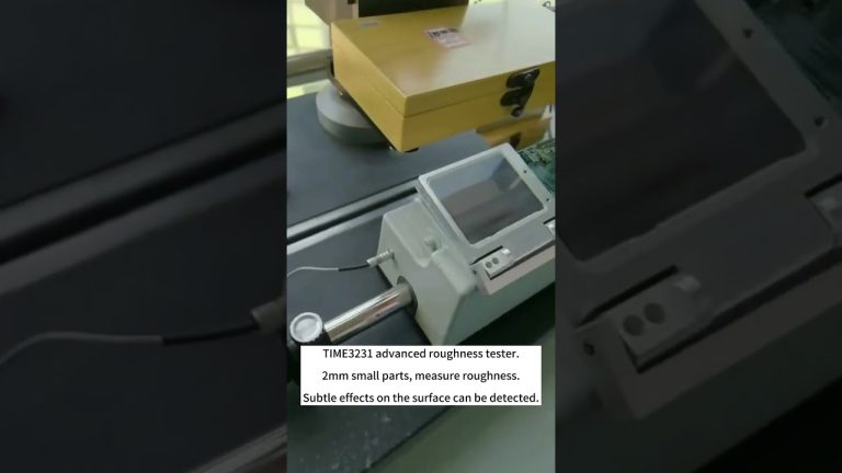
(1) The surface roughness of the workpiece is too large, resulting in poor coupling between the probe and the contact surface, low reflected echo, or even failure to receive echo signals. For in-service equipment and pipelines with surface corrosion and extremely poor coupling effect, the surface can be treated by sanding, grinding, filing and other methods to reduce the roughness. At the same time, the oxide and paint layer can also be removed to reveal the metallic luster, so that the probe and the object under test can achieve a good coupling effect through the coupling agent.
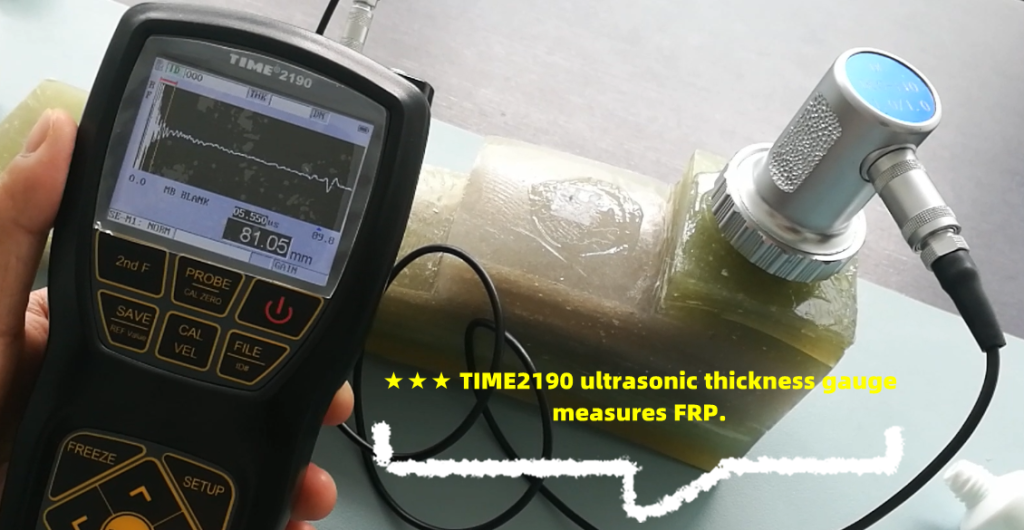
(2) The radius of curvature of the workpiece is too small, especially when measuring the thickness of small-diameter pipes. Because the surface of the commonly used probe is flat, the contact with the curved surface is point contact or line contact, and the sound intensity transmittance is low (poor coupling). A special ultrasonic thickness gauge probe for small pipes (6mm) can be used to measure curved materials such as pipes more accurately.
(3) The detection surface is not parallel to the bottom surface, and the sound wave encounters the bottom surface and scatters, and the probe cannot receive the bottom wave signal.
(4) Castings and austenitic steel have uneven structure or coarse grains, and the ultrasonic wave produces severe scattering attenuation when passing through them. The scattered ultrasonic wave propagates along a complex path, which may cause the echo to be annihilated, resulting in no display. A special probe for coarse grains with a lower frequency (2.5MHz) can be used.
(5) The contact surface of the probe has a certain wear. The surface of the commonly used thickness gauge probe is acrylic resin. Long-term use will increase its surface roughness, resulting in decreased sensitivity and incorrect display. You can use 500# sandpaper to polish it to make it smooth and ensure parallelism. If it is still unstable, consider replacing the probe.
(6) There are a large number of corrosion pits on the back of the object being measured. Because there are rust spots and corrosion pits on the other side of the object being measured, the sound wave is attenuated, resulting in irregular changes in the reading, and even no reading in extreme cases.
(7) There are sediments in the object being measured (such as pipes). When the acoustic impedance of the sediment and the workpiece is not much different, the thickness gauge displays the wall thickness plus the sediment thickness.
(8) When there are defects inside the material (such as inclusions, interlayers, etc.), the display value is about 70% of the nominal thickness. At this time, an ultrasonic flaw detector can be used to further detect defects.
(9) The influence of temperature. Generally, the sound velocity in solid materials decreases as the temperature increases. Experimental data show that the sound velocity decreases by 1% for every 100°C increase in hot materials. This situation is often encountered for high-temperature in-service equipment. A special high-temperature probe (300-600°C) should be used. Do not use an ordinary probe.
(10) Laminated materials, composite (inhomogeneous) materials. It is impossible to measure uncoupled laminated materials because ultrasonic waves cannot penetrate uncoupled spaces and cannot propagate at a uniform speed in composite (inhomogeneous) materials. For equipment made of multiple layers of materials (such as urea high-pressure equipment), special attention should be paid when measuring thickness. The thickness gauge only indicates the thickness of the layer of material in contact with the probe.
(11) The influence of coupling agent. Coupling agent is used to remove the air between the probe and the object to be measured so that ultrasonic waves can effectively penetrate the workpiece to achieve the purpose of detection. If the type or method of use is improper, it will cause errors or the coupling mark will flash and measurement will be impossible. Choose the appropriate type according to the usage. When used on a smooth material surface, a low-viscosity coupling agent can be used; when used on a rough surface, a vertical surface, and a top surface, a high-viscosity coupling agent should be used. High-temperature coupling agent should be used for high-temperature workpieces. Secondly, the coupling agent should be used in an appropriate amount and applied evenly. Generally, the coupling agent should be applied to the surface of the material to be measured. However, when the measurement temperature is high, the coupling agent should be applied to the probe.
(12) Wrong sound velocity selection. Before measuring the workpiece, preset its sound velocity according to the material type or measure the sound velocity based on the standard block. When the instrument is calibrated with one material (the test block is usually steel) and then measured with another material, an incorrect result will be produced. It is required to correctly identify the material and select the appropriate sound velocity before measurement.
(13) The influence of stress. Most of the equipment and pipelines in service have stress. The stress state of solid materials has a certain influence on the sound velocity. When the stress direction is consistent with the propagation direction, if the stress is compressive stress, the stress effect increases the elasticity of the workpiece and accelerates the sound velocity; conversely, if the stress is tensile stress, the sound velocity slows down. When the stress is not consistent with the propagation direction of the wave, the particle vibration trajectory is disturbed by the stress during the wave wave, and the propagation direction of the wave is deviated. According to the data, generally, as the stress increases, the sound velocity increases slowly.
(14) The influence of oxides or paint coatings on the metal surface. Although the dense oxide or paint anti-corrosion layer produced on the metal surface is tightly bonded to the base material without a visible interface, the speed of sound propagation in the two substances is different, resulting in errors, and the size of the error varies with the thickness of the covering.