1.1 Measurement range
Table 9-10 Defect classification table by indication length mm
| Grade | Plate thickness T | Plate thickness T |
| 15-40 | >40~80 | |
| Ⅰ | ≤10 | ≤1/4T |
| Ⅱ | ≤15 | ≤1/3T |
| Ⅲ | Refers to those whose length is not greater than Grade II | Refers to those whose length is not greater than Grade II |
Ⅲ refers to those with length greater than level Ⅱ
Note: When the thickness of the plates on both sides of the butt weld is different, the thinner one shall prevail.
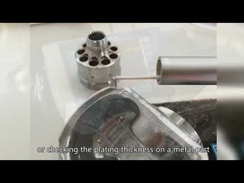
This chapter applies to ultrasonic measurement of the thickness of pressure vessel plates, heads, cylinders and nozzles using digital direct-reading ultrasonic thickness gauges or type A pulse reflection ultrasonic flaw detectors.
1.2 Sound velocity range of several main materials
The sound velocity range of several main materials is shown in Table 10-1. When using, if necessary, the actual sound velocity of the material should be measured.
Table 10-1 Sound velocity of several main materials m/s When measuring with a double crystal straight probe, the direction of the split surface is rotated 90° and the same measuring point is measured twice. The smaller value shall prevail.
1.8.3 ф30mm multi-point measurement method
When the measured value is unstable, multi-point measurement is performed within a range of 30mm with one measuring point as the center. The minimum value is HE.
1.8.4 Method for measuring pipe wall thickness
When measuring with a single straight probe, the center line of the probe should be perpendicular to the center line of the pipe axis and pass through the center of the pipe. When measuring with a double crystal straight probe, the probe split line must be perpendicular to the center line of the pipe axis.
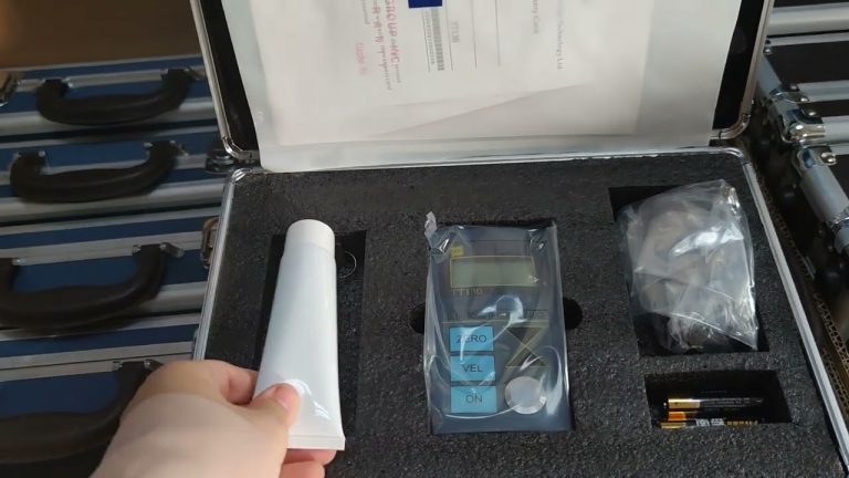
1.3 Instruments and probes
1.3.1 The accuracy of the ultrasonic thickness gauge should reach ±(T% + 0.1) mm, where T is the wall thickness.
1.3.2 Ultrasonic thickness measurement usually uses a direct contact single crystal straight probe, and can also use a single crystal straight probe with a delay block and a dual crystal straight probe.
1.3.3 The wall thickness measurement of high-temperature test pieces requires a special high-temperature probe.
1.4 Calibration test block
1.4.1 The basic requirements and dimensions of the test block are shown in Figure 10-1.
1.4.2 When measuring the thickness of a curved workpiece, a test block with the same curvature should be used, or the flat test block should be corrected.
1.5 Coupling agent
According to the surface condition and acoustic impedance of the workpiece to be measured, a coupling agent with no bubbles and appropriate viscosity should be selected, such as glycerin, engine oil, silicone, water glass and paste. If the surface of the workpiece is rough, a thicker coupling agent should be selected.
1.6 Instrument calibration
1.6.1 Calibration of ultrasonic thickness gauge
a. Use a step test block and calibrate at a thickness close to the maximum value of the thickness to be measured and the minimum value of the thickness to be measured (or 1/2 of the maximum value of the thickness to be measured).
b. Place the probe on a thicker test block and adjust the “sound velocity calibration” knob so that the thickness gauge display reading is close to the known value.
c. Place the probe on a thinner test block and adjust the “zero calibration” knob so that the thickness gauge display reading is close to the known value.
d. Repeatedly adjust so that both ends of the range get correct readings, and the instrument is debugged.
e. If the sound velocity of the material is known, the sound velocity value can be adjusted in advance, and then on the test block attached to the instrument, adjust the “zero calibration” knob so that the instrument displays water as the thickness of the test block, and the instrument is debugged.
1.6.2 Calibration of ultrasonic flaw detector
a. Same as 1.6.1 a.
b. Place the probe on a thicker test block and adjust the instrument’s “scan range” knob until the bottom surface echo appears at the corresponding scale position.
c. Place the probe on a thinner test block and adjust the instrument’s “delayed scan” knob until the bottom surface echo appears at the corresponding scale position.
d. Repeat the adjustment until the bottom surface echo on both the thick and thin test blocks appears at the correct scale position, and the instrument is adjusted.
1.7 Measurement preparation
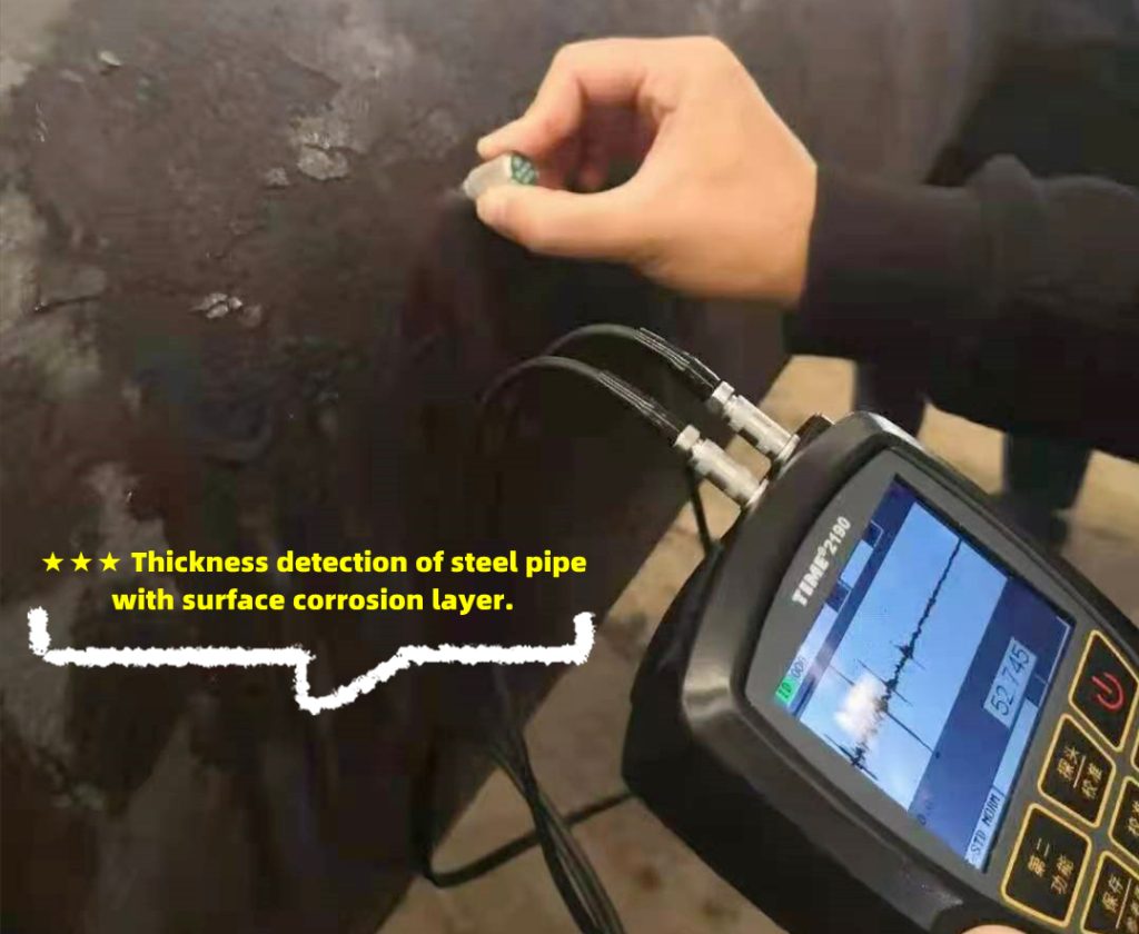
Floating rust, scales or partially detached coatings on the measurement surface should be cleaned, and if necessary, they can be properly polished with a grinding wheel.
1.8 Measurement method
The method of performing only one measurement at the measurement point is generally applicable to single crystal straight probes.
1.8.2 Secondary measurement method
1.9 Treatment of abnormal measurement values
When using an ultrasonic thickness meter for measurement, abnormal values may sometimes appear, which must be properly handled.
1.9.1 No displayed value
If the radius of curvature of the workpiece is too small or there is a lot of pitting on the back, the thickness gauge will not display a value. At this time, an ultrasonic flaw detector should be used for auxiliary measurement.
1.9.2 The displayed value is about twice the actual thickness
The wall thickness of the workpiece is less than 3mm, and the back is relatively smooth. In order to avoid the display value of the thickness gauge sometimes being twice the actual thickness, a small range probe or a special probe should be used.
1.9.3 The displayed value is smaller than the actual thickness
When there are internal defects such as inclusions and interlayers, the thickness gauge display value is often less than 70% of the nominal thickness. At this time, an ultrasonic flaw detector should be used to detect the area around the measuring point to confirm whether it is affected by the defect. The probe can be a straight probe or an oblique probe.
1.10 Report
The report shall at least include the following contents:
a. Workpiece name, material, number, and commissioning unit;
b. Instrument model, probe, test block, coupling agent, and measurement method;
G. Measurement location and data, measurement location sketch, maximum and minimum values of measurement data,
d. Operator, checker;
e. Measurement date.