Ultrasonic hardness tester definition
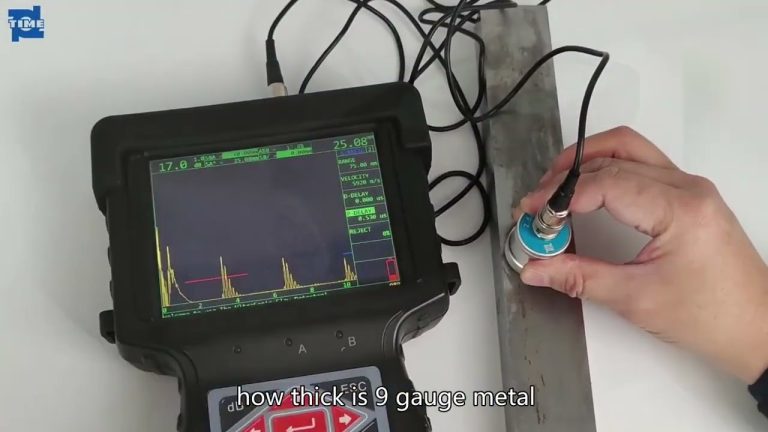
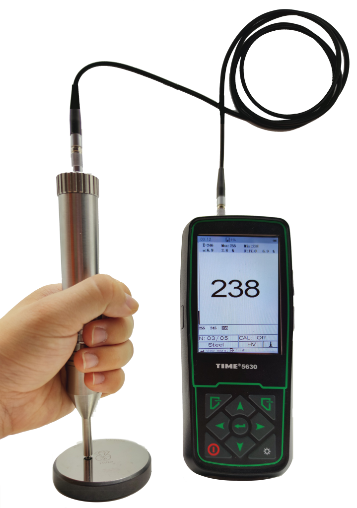
The ultrasonic hardness tester brings the sensor probe into contact with the tested piece. Under uniform contact pressure, the resonant frequency of the sensor changes with the indentation depth (i.e. hardness). The purpose of measuring the hardness is achieved by measuring the change in frequency.
This method It causes minimal damage to the part under test and is a non-destructive measurement. At the same time, it adopts electromechanical conversion signal pickup method.
Based on the principle of ultrasonic measurement, an intelligent digital display ultrasonic hardness tester with high precision and powerful functions has been developed.
Basic principles of ultrasonic hardness tester
- Working principle of sensor
The sensor is composed of a piezoelectric crystal, an excitation coil, a sensor rod, a diamond cone, etc. One end of the sensor rod is fixed with a large mass rigid body, and the other end is inlaid with a diamond cone indenter. When the indenter is not in contact with the measured object (as shown in Figure 1a), it is in a state of free vibration. At this time, the fixed end of the sensor rod will be the node of vibration, and the end of the indenter will become the antinode of vibration due to the largest amplitude. point, the length of the rod is equal to 1/4 of the vibration wavelength, and the frequency at this time is the free oscillation frequency of the sensor rod. When the indenter end of the sensor rod is completely clamped by the test piece (as shown in Figure 1c), ideally both ends of the sensor rod will become vibration wave nodes, and the length of the rod is equal to 1/2 of the vibration wavelength. The frequency at this time is Twice when the indenter end is in a free state. When the indenter presses onto the tested piece, it is between the above two situations (as shown in Figure 1b). Under the action of a fixed load, for test pieces with the same elastic modulus , the lower the hardness, the deeper the indentation, the smaller the wavelength of vibration, and the higher the vibration frequency of the rod. By measuring the change in the vibration frequency of the sensor rod, the hardness of the tested piece can be determined. It should be pointed out that the elasticity of the test piece Different modulus will also affect the vibration state of the sensor rod. Therefore, the elastic modulus of the tested block should be consistent with the standard test block used for calibration to ensure test accuracy. - Excitation oscillation source and output signal processing of the probe
This is a standard positive feedback oscillator. The oscillating current output by BG2 flows through the coil in the probe, and the generated alternating magnetic field drives the sensor rod to vibrate. The vibration of the rod acts on the piezoelectric ceramic, and the piezoelectric ceramic outputs a The “amplified” electrical signal (sinusoidal signal) is then fed back to BG1 to form self-excited oscillation. After the circuit starts to oscillate, the oscillation frequency is mainly determined by the rod load and spring elastic coefficient in the sensor.
The output signal of the probe is an approximate sine wave signal with a peak value of about 0.4V. After amplification and shaping, it is sent to the T0 terminal of 89C for counting to calculate the frequency. After data processing, the measured hardness value can be obtained.