อีเมล์:
วอตส์แอพ: 008615201625204 timehardnesstester@gmail.com
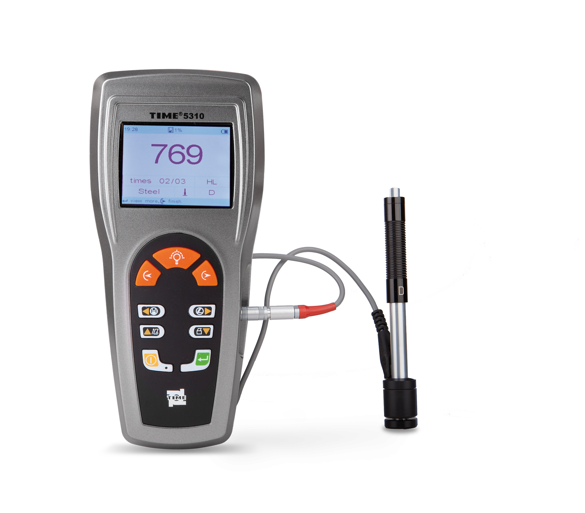
ใช้กันอย่างแพร่หลายในไซต์การผลิตเพื่อวัดความหยาบผิวของชิ้นส่วนต่างๆ ที่แปรรูปด้วยเครื่องจักร คำนวณพารามิเตอร์ที่เกี่ยวข้องตามเงื่อนไขการวัดที่เลือก และแสดงพารามิเตอร์การวัดทั้งหมดอย่างชัดเจน
วิธีการตัดแสง: แถบแสงที่เกิดขึ้นหลังจากผ่านร่องจะถูกฉายลงบน พื้นผิวที่จะวัด และความหยาบของพื้นผิวจะวัดตามเส้นโค้งรูปร่างที่เกิดจากเส้นตัดกับพื้นผิวที่จะวัด (รูปที่ 3)
หลังจากแสงที่ปล่อยออกมาจากแหล่งกำเนิดแสงผ่านคอนเดนเซอร์ ให้กรีด และเลนส์ใกล้วัตถุ 1 ช่องจะถูกฉายลงบนพื้นผิวที่วัดได้ที่มุมเอียง 45° เพื่อสร้างโปรไฟล์หน้าตัดของพื้นผิวที่วัด ซึ่งจากนั้นจะถูกขยายและฉายลงบนพื้นผิวที่วัดผ่านเลนส์ใกล้วัตถุ 2 บน เส้นเล็ง
ใช้ช่องมองภาพไมโครมิเตอร์และดรัมอ่านค่า (ไม่แสดงในรูป) เพื่ออ่านค่า H ก่อน จากนั้นจึงคำนวณค่า H เครื่องมือวัดความหยาบผิวที่ใช้วิธีนี้เรียกว่ากล้องจุลทรรศน์ส่วนแสง เหมาะสำหรับการวัดความหยาบผิวของ RZ และ Ry ระหว่าง 0.8 ถึง 100 ไมครอน ต้องใช้การเลือกจุดด้วยตนเองและมีประสิทธิภาพการวัดต่ำ
วิธีการรบกวนใช้หลักการของการรบกวนของคลื่นแสง (ดูคริสตัลแบน เทคโนโลยีการวัดความยาวเลเซอร์) เพื่อแสดงข้อผิดพลาดรูปร่างของพื้นผิวที่วัดเป็นรูปแบบขอบการรบกวน และใช้ กล้องจุลทรรศน์ที่มีกำลังขยายสูง (สูงสุด 500 เท่า) เพื่อวัดชิ้นส่วนที่มองเห็นด้วยกล้องจุลทรรศน์ของขอบสัญญาณรบกวนเหล่านี้
วัดหลังการขยายเพื่อให้ได้ความหยาบของพื้นผิวที่วัดได้ เครื่องมือวัดความหยาบผิวที่ใช้วิธีนี้เรียกว่ากล้องจุลทรรศน์รบกวน วิธีนี้เหมาะสำหรับการวัดความหยาบผิวด้วย Rz และ Ry 0.025 ถึง 0.8 ไมครอน
——————————————————————————————————–
Widely used in production site to measure surface roughness of various machinery-processed parts, calculate corresponding parameters according to selected measuring conditions and clearly display all measurement parameters.
Light section method: The light band formed after passing through the slit is projected onto the surface to be measured, and the surface roughness is measured based on the contour curve formed by the intersection line with the surface to be measured (Figure 3).
After the light emitted from the light source passes through the condenser, slit, and objective lens 1, the slit is projected onto the measured surface at an inclination angle of 45° to form a cross-sectional profile figure of the measured surface, which is then amplified and projected onto the measured surface through objective lens 2. on the reticle.
Use the micrometer eyepiece and reading drum (not shown in the figure) to first read the H value, and then calculate the H value. The surface roughness measurement tool that applies this method is called a light-section microscope. It is suitable for measuring surface roughness of RZ and Ry between 0.8 and 100 microns. It requires manual point selection and has low measurement efficiency.
The interference method uses the principle of light wave interference (see flat crystal, laser length measurement technology) to display the shape error of the measured surface as an interference fringe pattern, and uses a microscope with high magnification (up to 500 times) to measure the microscopic parts of these interference fringes.
Measure after magnification to obtain the measured surface roughness. The surface roughness measurement tool that applies this method is called an interference microscope. This method is suitable for measuring surface roughness with Rz and Ry of 0.025 to 0.8 microns.