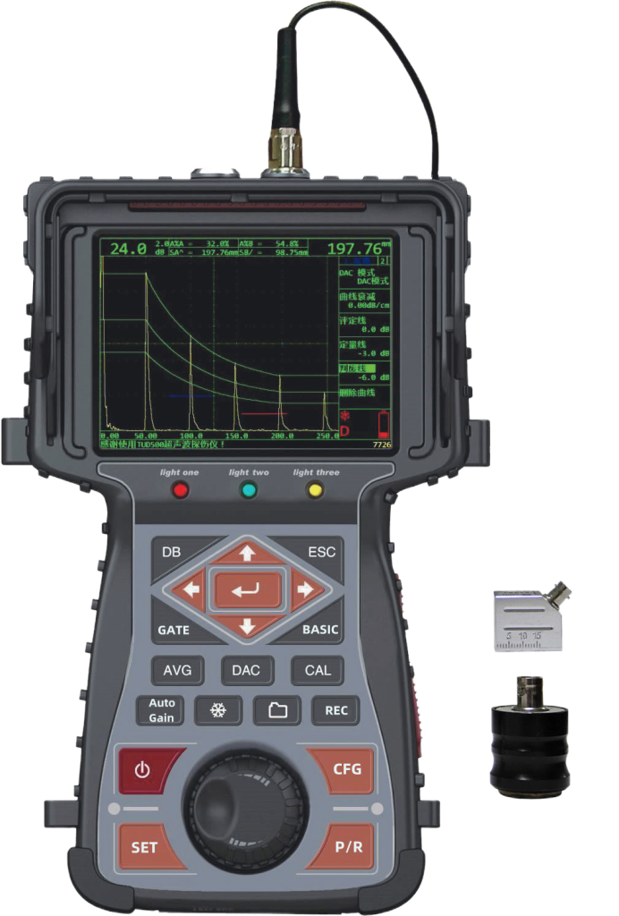
TUD500 Digital Ultrasonic Flaw Detector The digital ultrasonic flaw detector has the salient features of “simpler menus, richer flaw detection functions, more user-friendly man-machine dialogue mode, and faster operation”, portability, durability, reliability, The operational stability is even more top-notch at home and abroad. Jinan Sanmu Scientific Instrument Co., Ltd. will provide you with continuous software updates to make the ultrasonic flaw detector more powerful and better able to meet your needs and realize your “standardized” and “personalized” Flaw detection ideas.
TUD500 digital ultrasonic flaw detector can quickly, conveniently, non-destructively and accurately detect and locate various defects inside the workpiece, such as pores, blisters, inclusions, folds, cracks, lack of fusion and lack of penetration of welds in metal materials, etc. Assessment and diagnosis. It also has the function of circumferential flaw detection on workpieces such as shafts, cylinders, seamless steel pipes, straight seam welded pipes, etc., and is widely used in scientific research, electric power, petrochemicals, boilers and pressure vessels, steel structures, military industry, aerospace, and railway transportation. , automobiles, machinery and other fields.
Taking the TUD500 ultrasonic flaw detector as an example, we will introduce how to set the gate of the digital ultrasonic flaw detector.
The most prominent feature of the digital ultrasonic flaw detector is that it can convert analog quantities related to reflected waves into digital signals, display them on the screen, and automatically perform measurements and calculations. When the instrument is required to compare and calculate a certain echo, someone needs to “tell” it which echo it is tracking. We agreed to use a “gate” to lock the echo to be measured. The instrument processes and calculates the echo within the gate, and displays all parameters of the echo in real time (including sound path distance, horizontal distance and vertical distance, as well as echo height and equivalent dB , equivalent size and other data). .
This instrument is designed with two gates: Gate A and Gate B. Gate A is a wave entrance gate (fixed to wave entrance alarm), its main purpose is to display the echo status data and alarm in the gate; Gate B can be set to wave entrance alarm, wave loss alarm or closed (repeatedly press the [Gate] key to Switch gate A and B). The user can select any gate as the current gate.
The default current gate of the instrument is gate A. When the user wants to select gate B as the current gate, the alarm logic of gate B must first be set to wave entry or wave loss, and the gate selection will automatically change to gate B. On the screen, gate A and gate B are displayed in different colors (gate A is red, gate B is green).
The starting point of the gate is to adjust the starting position of the current gate, gate → F1. The user can turn the knob to move the gate left and right as needed to lock the characteristic echo.
Gate Width Adjust the left and right width of the current gate, gate → F2, and then turn the wheel to adjust as needed.
Gate height refers to the percentage of the gate relative to the full width of the echo display area. The adjustment range of the gate height is 0~100%. Gate→F3, then turn the knob to adjust as needed.
The specific setting method of gate alarm is as follows:
- Set gate alarm logic
Each gate can be triggered by one of two alarm conditions. That is, when the A-scan waveform passes through the gate or no echo passes through the gate, the gate alarm is triggered. Follow these steps to set up the gate logic:
Step 1: Press the [Gate] key to enter the gate menu. (Press the [Gate] key repeatedly to switch between gates A and B)
Step 2: Press [F5 key] to select the alarm logic function item.
Step 3: Press [F5 key] repeatedly to select the following 4 alarm logics. (You can also rotate the knob to select alarm logic)
Incoming wave – when the A-scan signal passes through the gate
Lost wave – when no A-scan signal passes through the gate
Measurement – only measurement, no alarm function
Off – Turn off measurement and alarm functions - Alarm mode: “sound” and “light”
Gates A and B can set alarms respectively. When a gate alarm is activated, one or more of the following situations will occur:
The alarm indicator light (A) on the front panel of the ultrasonic flaw detector lights up.
The alarm (buzzer) sounds. - Switch the alarm sound on and off
Step 1: Press the [Gate] button. (Note: Press the [Gate] key repeatedly to switch between gates A and B)
Step 2: Press the [F4] key to select the alarm sound function item.
Step 3: Press the [F4] key repeatedly to turn on or off the alarm sound. (Or turn the knob to turn the alarm sound on or off)